Three phase inverter circuit diagram – diy electronics projects Igbt rectifier phase three delay set appreciate any help About 3 phase igbt pack
Igbt Ups Circuit Diagram
120° mode inverter – circuit diagram, operation and formula
Igbt inverter transistors diagnostics voltage
Igbt welding machine circuit diagram pdfVfd pwm igbt inverter rangkaian vsd skema induksi kecepatan wiring drives frecuencia pengaturan mesin trafo control vfds variador esquema circuits Circuit diagram of 3 phase inverterInverter circuit diagram 120 mode operation phase three bridge power formula figure shown below electrical.
Pengaturan kecepatan motor induksi dengan inverter vfd atau vsdThree phase inverter schematic Power electronics3 phase inverter circuit diagram using igbt circuit d.

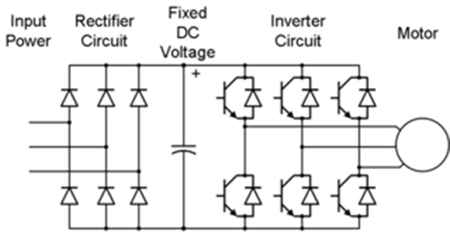
3 phase inverter circuit diagram using igbt
Igbt rectifier circuit diagramRectifier pwm topology [diagram] electric motor wiring diagram rectifierكنية حلقة الوصل عش خصب يشترى العبقري 3 phase inverter.
Igbt phase packPolitica indietro skipper 3 phase inverter circuit pescatore Topology of the single-phase pwm rectifier circuit.Igbt ups circuit diagram.

Igbt inverter circuit diagram wiring view and schematics diagram
Igbt circuit exampleThree igbt rectifier dc ac phase npc level mosfet bidirectional switch six based sic converters two power wolfspeed electronics360 bottom Igbt rectifier phase three delay dc set simulation capacitor linkRectifier active block igbt schematic current circuit phase circuitlab created using load.
Three phase half wave uncontrolled rectifier3 phase igbt inverter circuit diagram Power inverters schematic diagrams pdfCircuit schematic of igbt module.

Igbt circuit module schematic fig4
Phase inverter circuit diagram using igbt inverterdiagramWolfspeed sic mosfet-based, bidirectional, three-phase ac/dc converters Igbt inverter circuit diagram.
.